
Products
Oxygen Sensors
Product Overview
The oxygen sensor, also known as the O2 or lambda sensor, is a critical feedback device in the internal combustion engine exhaust system. Its essential function is to monitor exhaust oxygen levels in order to maintain the ideal air-fuel ratio, which optimizes fuel efficiency, enhances engine performance, and minimizes harmful emissions. Deviations from this ideal ratio result in specific pollutants: excessive fuel produces hydrocarbons (HC) and carbon monoxide (CO), while insufficient fuel increases nitrogen oxides (NOx). Three main types of sensors are widely used to meet varying control requirements: Narrow-band Type, Air/Fuel Ratio Type, and Wide-Band Oxygen Sensors. Each is engineered with distinct principles and designs, catering to applications ranging from basic regulation to high-precision tuning. Employing a high-quality oxygen sensor ensures precise mixture control by leveraging proven technology for fast response and long-term durability, which is fundamental to maintaining emission compliance and overall system reliability.
Product Application
Oxygen sensors in automotive exhaust systems have primary functions as below:
- Three-Way Catalytic Converter Operation
- On-Board Diagnostics (OBD)
- Air-Fuel Ratio Control
- Enable Emissions Diagnostics
Types of Oxygen Sensors
Narrow-band Type Oxygen Sensors (Narrow-band)
Narrow-band oxygen sensors are electrochemical devices based on a zirconia (ZrO₂) solid electrolyte. They generate a characteristic binary voltage signal in response to exhaust oxygen concentration: • Rich mixture (low O₂): 0.8–1.0V • Lean mixture (high O₂): 0.1–0.3V While conventional designs rely on an external reference air channel to establish an oxygen baseline, modern variants employ a pumped O₂ reference architecture. In this approach, a precisely controlled ion current (typically ~20μA) is used to create an internal oxygen reference, eliminating the need for a physical air channel. This sealed design greatly enhances resistance to contamination from oil, fuel additives, or water ingress. Regardless of reference method, all Narrow-band type sensors deliver the same fundamental function: providing the ECU with a stoichiometric switching signal (around λ=1) for closed-loop fuel control and catalyst monitoring. Their proven reliability, fast response, and cost-effectiveness make them a cornerstone of gasoline engine emission systems worldwide.
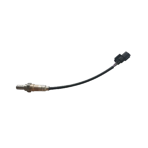
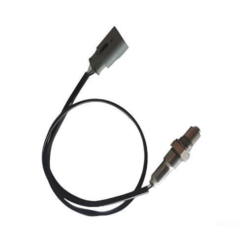
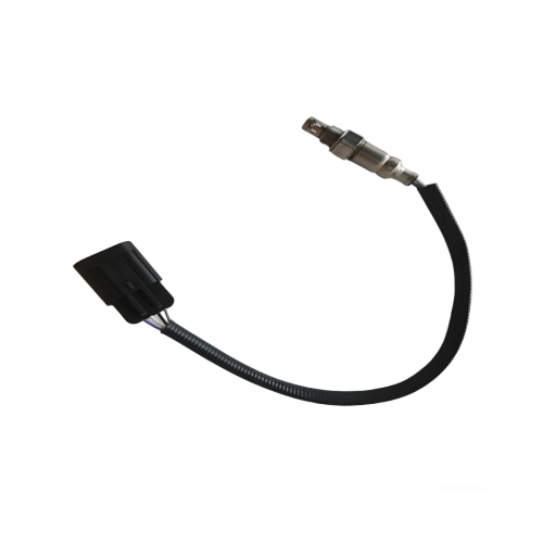
Product Series
Product Features & Installation
Performance Parameters
| Parameter | SA01 | SA02 | FLPO | SA03 | SA04 | SA05 | SA11 | FLPO-H |
|---|---|---|---|---|---|---|---|---|
Signal Output
450°C | ≥750mV (λ=Rich)
≤200mV (λ=Lean) | |||||||
Light-off Time | ≤60s (unheated type, exhaust gas temperature ≥450°C) | Thimble (heated): Typically 20–50 seconds from engine start
Planar (heated): Typically 5–15 seconds from engine start | ||||||
Lambda Measurement Range | Exhaust gas Rich/Lean | |||||||
Response Time | Tlean/rich ≤100ms
Trich/lean ≤150ms | |||||||
Supply Voltage | Compatible with both 12V and 24V vehicle electrical systems | |||||||
Operating Exhaust Gas Temperature | 350°C ≤ Exhaust temperature ≤ 850°C (Valid for measurement accuracy) | |||||||
Lifespan | Validated by engine test (2000h equivalent to 100,000 km) | |||||||
Structural Features
| Parameter | SA01 | SA02 | FLPO | SA03 | SA04 | SA05 | SA11 | FLPO-H |
|---|---|---|---|---|---|---|---|---|
Sensing Element Material | Thimble/Planar | Planar | ||||||
Thread Specification | M18×1.5-6e | M12×1.25-6e | M18×1.5-6e | M12×1.25-6e | ||||
Installation Torque (apply anti-seize compound on threads) | 35 to 55 N·m | 20 to 30 N·m | 35 to 55 N·m | 20 to 30 N·m | ||||
Heated/Unheated | Unheated | Heated | ||||||
Heater Resistance (23°C) | NA | 4/6/9/13 Ω | 9 Ω | 3 Ω | 4/6/9 Ω | |||
Ground Type | Case ground | Isolated ground | Case/Isolated ground | Isolated ground | ||||
Number of Wires | 1 Wire | 2 Wire | 3 Wire | 4 Wire | ||||
Cable Length | Multiple specifications of wiring harnesses | |||||||
Connector Type | 1/2pin connector (Depending on product requirements) | 3/4pin connector (Depending on product requirements) | ||||||
Grommet Working Temperature | Continuous: ≤200°C
Short-term: 225°C
(Material: Silicone + Fiberglass braid) | |||||||
Connector Temp Rating | Continuous: ≤120°C | |||||||